Mano, M. M., Kime, C. R., &
Martin, T. (2015). Logic and computer design
fundamentals (5th ed.). Boston: Pearson.
| INPUT | OUTPUT | |
| A | B | A AND B |
| 0 | 0 | 0 |
| 0 | 1 | 0 |
| 1 | 0 | 0 |
| 1 | 1 | 1 |
module basic_and (a, b, out);
input a, b;
output out;
assign out = a & b;
endmodule
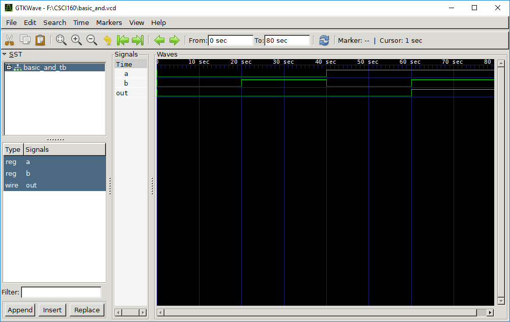
module basic_and_tb();
reg a, b;
wire out;
basic_and DUT (
.a(a),
.b(b),
.out(out)
);
initial begin
// Dump results of the simulation to basic_and.vcd
$dumpfile("basic_and.vcd");
$dumpvars;
a = 0;
b = 0;
#20
a = 0;
b = 1;
#20
a = 1;
b = 0;
#20
a = 1;
b = 1;
#20
$finish;
end
endmodule
If you look at the above description, notice that it is composed of
two modules, each of which starts with the keyword module
and ends with the keyword endmodule. The fundamental
descriptive unit in Verilog is the module, and a Verilog description
is separated into different modules. You could think of them as
rough equivalents of functions in other programming languages. The
first module above, called basic_and, is a description of
our basic AND gate. The second module, called basic_and_tb,
is what is known as a test bench, which is HDL code that
allows you to provide a documented, repeatable set of stimuli that
is portable across different simulators. To simulate our design, we
will need both the Device Under Test (DUT), which in this case is
our AND gate described in basic_and, and the stimulus
provided by the test bench.